Uml How to Show Continues in Seperate Diagram
In this post we discuss Sequence Diagrams. Unified Modelling Language (UML) is a modeling language in the field of software engineering which aims to set standard ways to visualize the design of a system. UML guides the creation of multiple types of diagrams such as interaction , structure and behaviour diagrams. A sequence diagram is the most commonly used interaction diagram. Interaction diagram – An interaction diagram is used to show the interactive behavior of a system. Since visualizing the interactions in a system can be a cumbersome task, we use different types of interaction diagrams to capture various features and aspects of interaction in a system. Sequence Diagrams – A sequence diagram simply depicts interaction between objects in a sequential order i.e. the order in which these interactions take place. We can also use the terms event diagrams or event scenarios to refer to a sequence diagram. Sequence diagrams describe how and in what order the objects in a system function. These diagrams are widely used by businessmen and software developers to document and understand requirements for new and existing systems.
Sequence Diagram Notations –
- Actors – An actor in a UML diagram represents a type of role where it interacts with the system and its objects. It is important to note here that an actor is always outside the scope of the system we aim to model using the UML diagram.
 Figure – notation symbol for actorWe use actors to depict various roles including human users and other external subjects. We represent an actor in a UML diagram using a stick person notation. We can have multiple actors in a sequence diagram. For example – Here the user in seat reservation system is shown as an actor where it exists outside the system and is not a part of the system.
  Figure – an actor interacting with a seat reservation system
 - Lifelines – A lifeline is a named element which depicts an individual participant in a sequence diagram. So basically each instance in a sequence diagram is represented by a lifeline. Lifeline elements are located at the top in a sequence diagram. The standard in UML for naming a lifeline follows the following format – Instance Name : Class Name
 Figure – lifelineWe display a lifeline in a rectangle called head with its name and type. The head is located on top of a vertical dashed line (referred to as the stem) as shown above. If we want to model an unnamed instance, we follow the same pattern except now the portion of lifeline's name is left blank. Difference between a lifeline and an actor – A lifeline always portrays an object internal to the system whereas actors are used to depict objects external to the system. The following is an example of a sequence diagram:
 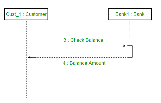 Figure – a sequence diagram
 - Messages – Communication between objects is depicted using messages. The messages appear in a sequential order on the lifeline. We represent messages using arrows. Lifelines and messages form the core of a sequence diagram. Messages can be broadly classified into the following categories :
 Figure – a sequence diagram with different types of messages
 - Guards – To model conditions we use guards in UML. They are used when we need to restrict the flow of messages on the pretext of a condition being met. Guards play an important role in letting software developers know the constraints attached to a system or a particular process. For example: In order to be able to withdraw cash, having a balance greater than zero is a condition that must be met as shown below.
 Figure – sequence diagram using a guard
A sequence diagram for an emotion based music player – 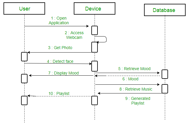 Figure – a sequence diagram for an emotion based music playerThe above sequence diagram depicts the sequence diagram for an emotion based music player:
- Firstly the application is opened by the user.
- The device then gets access to the web cam.
- The webcam captures the image of the user.
- The device uses algorithms to detect the face and predict the mood.
- It then requests database for dictionary of possible moods.
- The mood is retrieved from the database.
- The mood is displayed to the user.
- The music is requested from the database.
- The playlist is generated and finally shown to the user.
Uses of sequence diagrams –
- Used to model and visualise the logic behind a sophisticated function, operation or procedure.
- They are also used to show details of UML use case diagrams.
- Used to understand the detailed functionality of current or future systems.
- Visualise how messages and tasks move between objects or components in a system.
References – The sequence diagram – IBM Sequence Diagram – sparxsystems This article is contributed by Ankit Jain . If you like GeeksforGeeks and would like to contribute, you can also write an article using write.geeksforgeeks.org or mail your article to review-team@geeksforgeeks.org. See your article appearing on the GeeksforGeeks main page and help other Geeks. Please write comments if you find anything incorrect, or you want to share more information about the topic discussed above.
Source: https://www.geeksforgeeks.org/unified-modeling-language-uml-sequence-diagrams/
0 Response to "Uml How to Show Continues in Seperate Diagram"
Post a Comment